The Inside of the NPXY100A piezo stage
I have been rather unsure lately how the power amplifer actually hooks up to the piezo. The specification I have for it says the amplifier puts out between -30 and 150 v. It is unclear to me if the piezo in the stage ever actually sees a negative voltage, or if the -30 volts is the ground of the piezo. I do know that when the low voltage input is zero, the voltage across the high voltage outputs is about 75 volts. Most piezos I see only have two inputs and expect a positive voltage.
At any rate, I thought I could clarify some of this if I took the top cover off the piezo stage to have a peak inside to see what the electrical connection to the piezo looks like. You can see it in Figure~1. It looks like the three hex bolts provide some kind of adjustment or calibration. They are actually exposed through the stages cover. I am really curious what they do.
What I do see is that the low side of the HV drive lines are (the are marked, e.g., "X Piezo Ref" on the PCB and the high voltage side is marked "X Piezo Drive" and it appears that there are only two connections to each piezo. While that makes sense, I don't really understand why they need to use -30 Volts as the piezo ground, rather than the common ground. I mean, the Apex PA85 MOSFET used to drive the thing is rated up to \(\pm\) 250 volts.
I was also able to measure the capacitance of the piezo directly at the connection points. I still get \(4\mu\)F. I also see that there is a resistor in parrallell with the piezo. I feel comfortable that I can use a \(4\mu\)F capacitor in parralell with a 0.5~M\(\Omega\) resistor as a dummy stage when trying to characterize the limitations of the power amplifier, in an effort to understand some of the bizzare things I've been seeing it do.
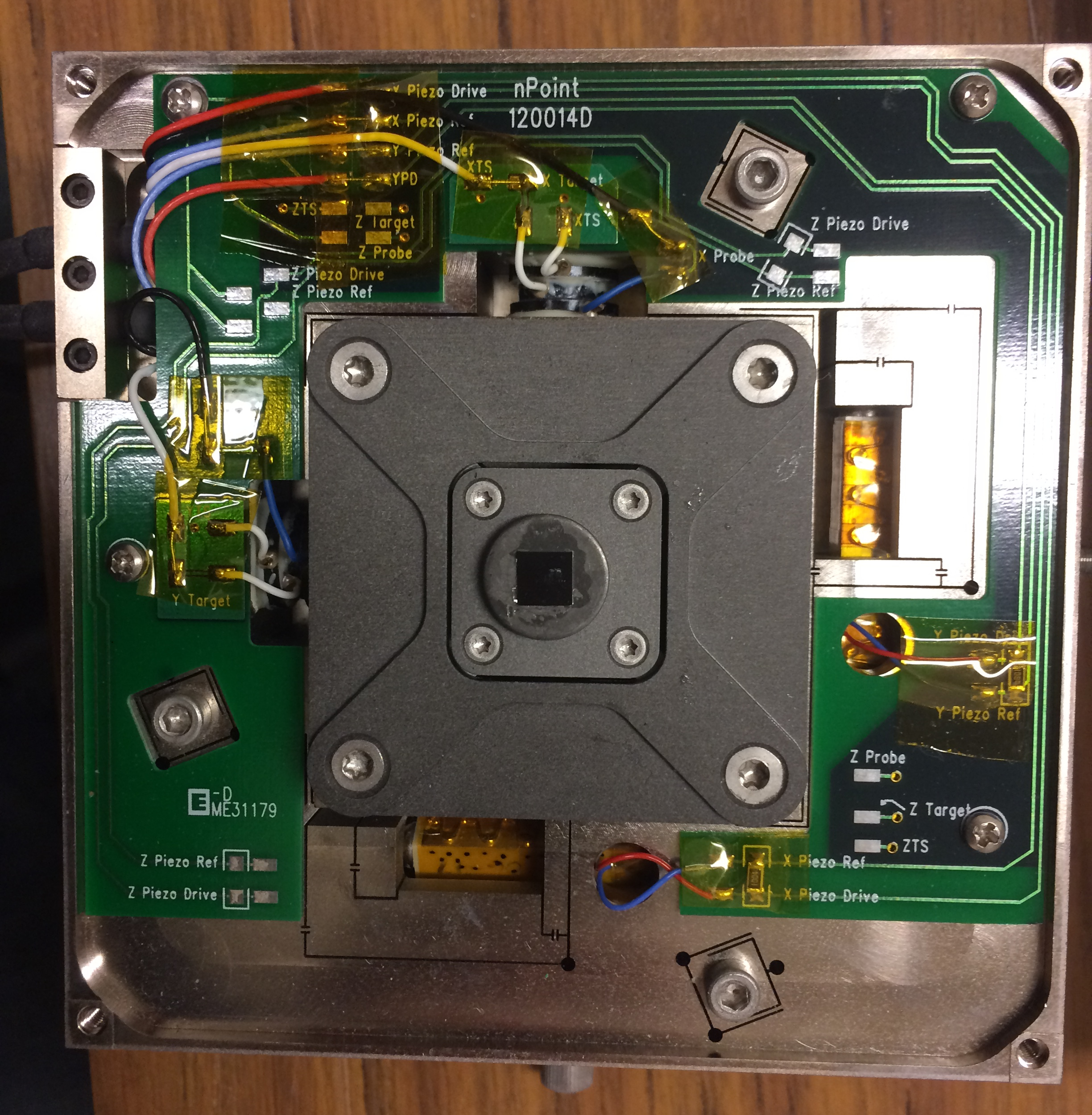
The dark lines you see on the aluminum is where it has actually been machined away providing the flexure part of the stage. It is mind blowing to me how little material is left in some places…
To make a long story short, I took the stage completely off the AFM base to get a better look. The trouble is that the stage is held onto a base plate via some kind of magnetic spring loaded contraptation, which is ultimately designed to let you do a course adjustment via thumb screws on each side of the stage. The base plate is then bolted to the AFM base. Once I had gotten the stage off, I could not get it back on. Sadly, I was to stressed out to think to take any photos. But essentially, you needed to be able to slide a spring loaded pin into a tiny registration divot, but part of the AFM blocked access. After fiddling with it for the better part of two hours, I decided the only way to re-assemble it was to first take the AFM's base plate off.
The tools I needed to do that were at home, so I decided to just put the stage on the table and continue on with my experiments. I decided I would first do I frequency response sweep to make sure everything was still in order.
What I saw shocked me.
The FRF of the stage unbolted from the AFM base is shown in Figure~2 as the solid blue curve. The dashed red curve is the FRF that I usually see.

I was convinced at first that I had broken something. After trying several things to make sure I wasn't crazy, I decided the only possibily where I hadn't damaged something was that the frequency responses are just that different when the stage is firmly bolted to a massive plate versus sitting free on the table. Essentially, my reasoning went, the massiv base must provide extra stiffness. By way of a rough analogy, think of firing a shotgun with it sitting loosely on a table vs firmly in the shooters shoulder…
So I took the AFM apart, bolted the stage back onto the base, re-assembled the AFM, and took another frequency response. Indeed, I get the familier looking FRF shown as the dashed red curve in Figure 2.
That was both terryfing and really fascinating to me.